GDMS AP6Ce
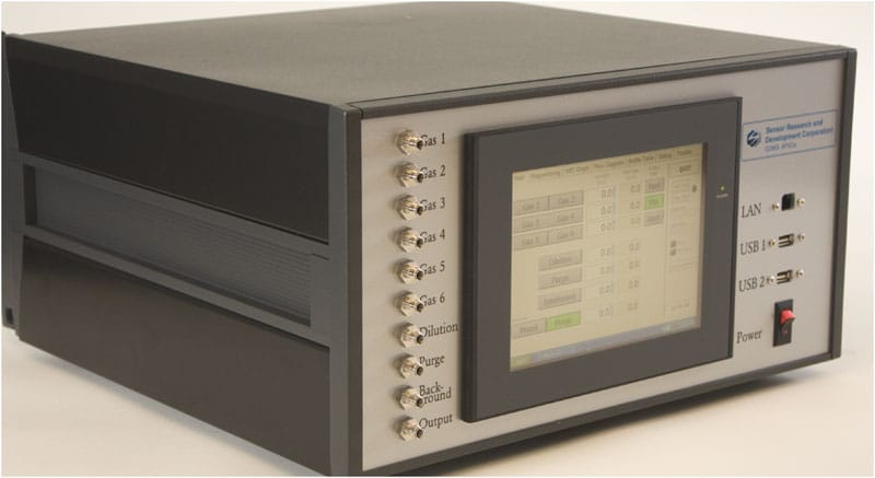
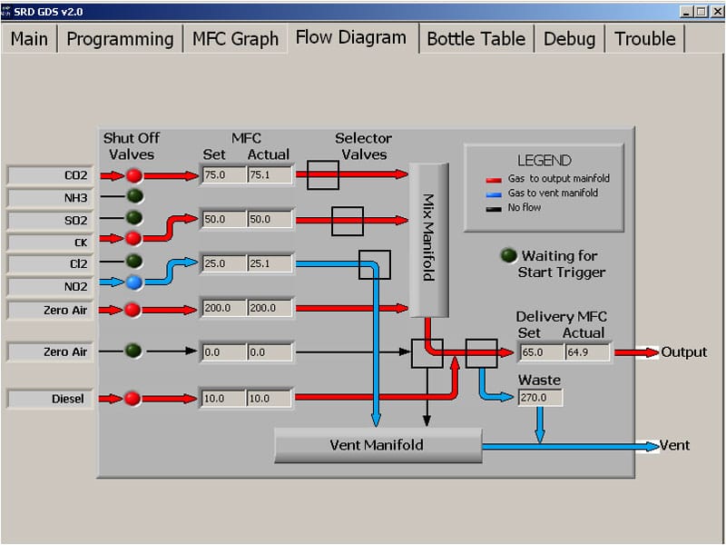
The GDMS AP6Ce is a six-channel gas delivery and mixing system that employs a modular, needs-driven approach and is also available in multiple configurations for all gas dilution and delivery requirements. The GDMS AP6Ce is fully automated and easily programmed via an embedded computer with a touch screen interface. Real-time diagnostics and feedback control, including visual display of active gas flow paths and dilution/mixing conditions, provides a total system status to the user and eliminates programming errors/conflicts. The GDMS AP6Ce is the solution to your laboratory gas testing and delivery needs.
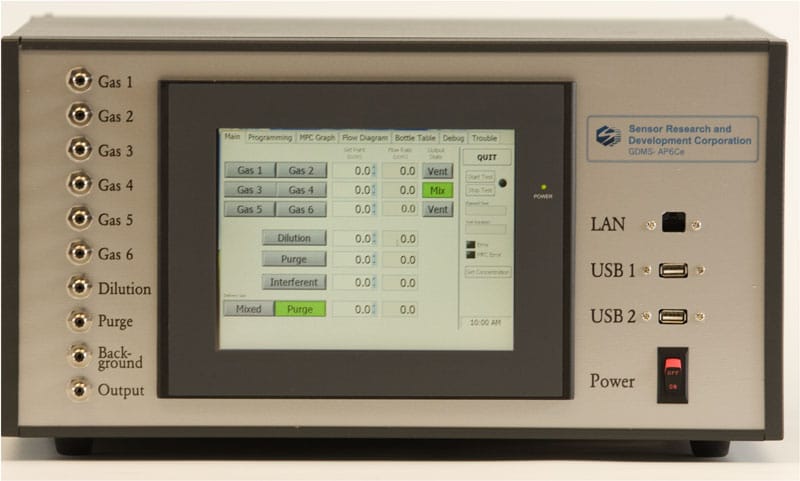
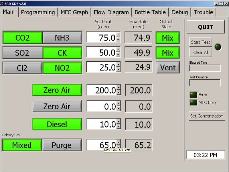
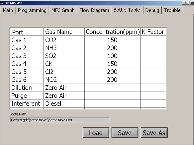
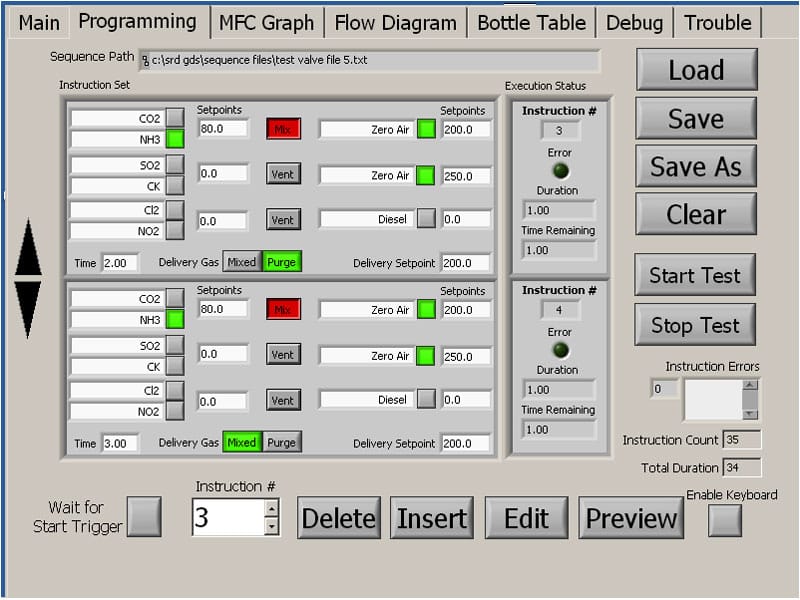
The GDMS AP6Ce allows for six gas inputs with three independent input mixing mass flow controllers (MFCs), one dilution MFC, one purge MFC, one interferent MFC, and a single output post-mixing MFC. The system also includes a pre-charge mixing manifold to virtually eliminate time delays between input gas selection and output exposure. The embedded touch-screen PC allows for ease-of-programming and ease-of-use (sample interface menus are shown below). There are also two USB ports and a LAN connection. The GDMS AP6Ce was designed as a universal gas delivery and mixing system that is easily configurable and adaptable to a wide range of applications.
(click images to view larger)
Intuitive Graphic User Interface
(click images to view larger)
Click here for downloadable PDF Spec Sheet
Technical Data
Features
- 6 Gas Inputs
- 3 Independent Mixing Mass Flow Controllers
- 1 Dilution Mass Flow Controller
- 1 Purge Mass Flow Controller
- 1 Interferent (Background) Mass Flow Controller
- 1 Output Mass Flow Controller
- Pre-charge Manifold
- Vent Manifold
- Embedded “Touch Screen” PC
- LAN Connection
- 2 USB Ports
Performance (Based on Alicat Scientific MFC Data)
- Maximum Flow Rates Available: 0.5 SCCM – 20 SLPM
- Operating Range: 1% to 100% full scale
- Accuracy: +/- 1% full scale
- Response Time: 100 milliseconds
- Operating Temperature: -10 to 50 °C
- Humidity Range: 0-100% (non-condensing)
- Operating Temperature: -10 to +50 ºC
Output File
Data that can be saved to an output file includes:
- MFC Pressure Reading (PSIA)
- MFC Temperature Reading (°C)
- MFC Mass Flow Reading (SCCM -SLPM)
- MFC Volumetric Flow Reading (SCCM-SLPM)
- Experiment Time
- System Date and Time
- Valve Positions
- Trigger State
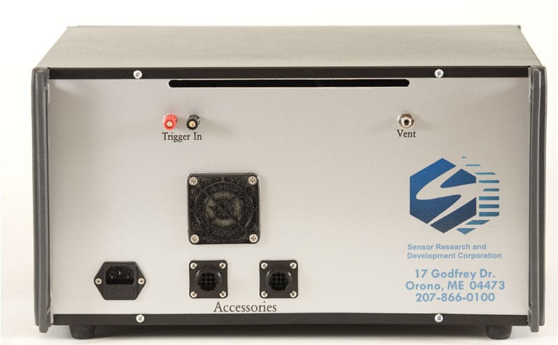
Trigger Connections
Digital (TTL) trigger connected via screw terminals mounted on front of GDS. It is used to read a low current 0-5 V signal.
Tubing and Connections
- SWAGELOK Bulkhead Input / Output Connectors (1/4″ typical)
- Supply Tubing: Stainless Steel
- Vent Tubing: Teflon
Gas Valves
- Programmable 2-Way and 3-Way Valves
- Operating Voltage: 24V DC
- Power Consumption: 7 Watts
- Max Operating Pressure: 30 PSI
- Body Material: Stainless Steel
- Wetted Surface: Viton®
Mechanical
- Weight: 48 lb
- Dimensions (w x h x d): 17″ x 9.25″ x 17.5″
- Volume: 1.593 ft3
Electrical
- Operating Voltage: 120V AC / 60 Hz
- Power Usage: 400 W (max)